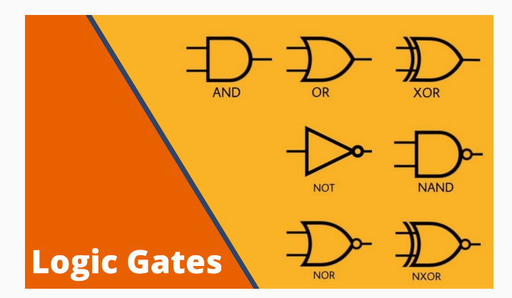
Introduce to logic gates
About Logic Gates
• • •
A logic gate is an idealized or physical device implementing a Boolean function, a logical operation performed on one or more binary inputs that produces a single binary output. Depending on the context, the term may refer to an ideal logic gate, one that has for instance zero rise time and unlimited fan-out, or it may refer to a non-ideal physical device[1] (see Ideal and real op-amps for comparison).
Logic gates are primarily implemented using diodes or transistors acting as electronic switches, but can also be constructed using vacuum tubes, electromagnetic relays (relay logic), fluidic logic, pneumatic logic, optics, molecules, or even mechanical elements. Now, most logic gates are made from MOSFETs (metal–oxide–semiconductor field-effect transistors).
With amplification, logic gates can be cascaded in the same way that Boolean functions can be composed, allowing the construction of a physical model of all of Boolean logic, and therefore, all of the algorithms and mathematics that can be described with Boolean logic.
Logic circuits include such devices as multiplexers, registers, arithmetic logic units (ALUs), and computer memory, all the way up through complete microprocessors, which may contain more than 100 million logic gates.
Compound logic gates AND-OR-Invert (AOI) and OR-AND-Invert (OAI) are often employed in circuit design because their construction using MOSFETs is simpler and more efficient than the sum of the individual gates.[
In Hindi
तर्कद्वार या लॉजिक गेट (logic gate) वह युक्ति है जिसका आउटपुट उसके इनपुट पर उपस्थित वर्तमान संकेतों या पूर्व संकेतों का कोई लॉजिकल फलन (Boolean function) हो। यह भौतिक युक्ति हो सकती है या कोई आदर्शीकृत युक्ति। आजकल अधिकतर अर्धचालक लॉजिक गेट प्रयोग किये जाते हैं किन्तु सिद्धान्ततः ये विद्युतचुम्बकीय रिले, तरल लॉजिक, दाब लॉजिक, प्रकाशिक लॉजिक, अणुओं आदि से भी बनाये जा सकते हैं।
बूलीय लॉजिक से जिन अल्गोरिथ्म का वर्णन किया जा सकता है उन्हें इन भौतिक गेटों से उन अल्गोरिद्मों को साकार रूप भी दिया जा सकता है (बनाया भी जा सकता है)।
जिस प्रकार एक दरवाजा (द्वार) दो अवस्थाओं – ‘खुला या बन्द’ में हो सकता है, उसी तरह लॉजिक गेट का आउटपुट भी ‘हाई या लो’ (High/Low) हो सकता है। लॉजिक गेट, ऐण्ड (AND) और ऑर (OR) जैसे सरल भी हो सकते हैं और एक कम्प्युटर जितना जटिल भी।
डायोड का उपयोग करके बनाया गया लॉजिक गेट सबसे सरल लॉजिक गेट है। किन्तु इसके केवल AND तथा OR गेट ही बनाये जा सकते हैं, ‘इन्वर्टर’ नहीं बनाया जा सकता। अतः इसे एक ‘अपूर्ण लॉजिक परिवार’ कह सकते हैं। इन्वर सहित सभी लॉजिक गेट बनाने में सक्षम होने के लिये किसी प्रकार के प्रवर्धक की जरूरत होगी। इसलिये ‘सम्पूर्ण लॉजिक परिवार’ बनाने के लिये रिले, निर्वात नलिका या ट्रांजिस्टर का प्रयोग अपरिहार्य है। बाइपोलर ट्रांजिस्टरों का प्रयोग करके बना लॉजिक परिवार रेजिस्टर-ट्रांजिस्टर लॉजिक (RTL) कहलाता है। आरम्भिक एकीकृत परिपथों में इसी का उपयोग किया गया था। इसके बाद विभिन्न दृष्टियों से सुधार करते हुए डायोड-ट्रांजिस्टर लॉजिक (DTL) और ट्रांजिस्टर-ट्रांजिस्टर लॉजिक (TTL) आये। अब लगभग सब जगह ट्रांजिस्टर का स्थान मॉसफेट (MOSFETs) ने ले लिया है जिससे आईसी कम स्थान घेरती है और काम करने के लिये कम उर्जा क्षय होती है। वर्तमान में प्रयुक्त लॉजिक परिवार का नाम कम्प्लिमेन्टरी मेटल-आक्साइड-सेमिकंडक्टर (CMOS) है।
AND Gate
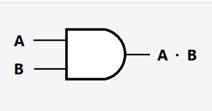
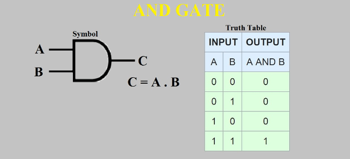
The AND gate is a basic digital logic gate that implements logical conjunction (∧) from mathematical logic – AND gate behaves according to the truth table above. A HIGH output (1) results only if all the inputs to the AND gate are HIGH (1). If not all inputs to the AND gate are HIGH, LOW output results. The function can be extended to any number of inputs.
Thuth table
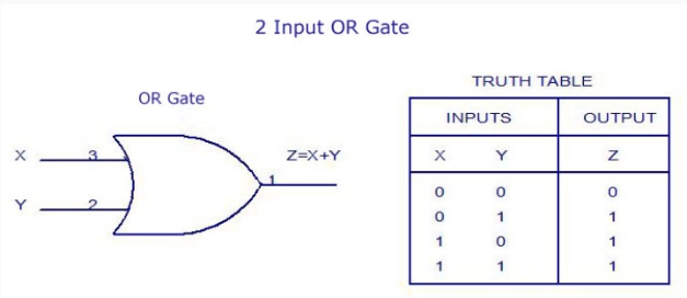
OR Gate

The OR gate is a digital logic gate that implements logical disjunction (∨) from mathematical logic – it behaves according to the truth table above. A HIGH output (1) results if one or both the inputs to the gate are HIGH (1). If neither input is high, a LOW output (0) results. In another sense, the function of OR effectively finds the maximum between two binary digits, just as the complementary AND function finds the minimum.[1]
In certain situations, the inputs to an OR gate (for example, in a full-adder) or to an XOR gate can never be both 1’s. As this is the only combination for which the OR and XOR gate outputs differ, an OR gate may be replaced by an XOR gate (or vice versa) without altering the resulting logic. This is convenient if the circuit is being implemented using simple integrated circuit chips which contain only one gate type per chip.
Truth table
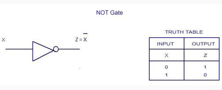
NOT Gate
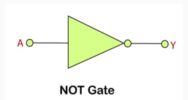
In digital logic, an inverter or NOT gate is a logic gate which implements logical negation. In mathematical logic it is equivalent to the logical negation operator (¬). The truth table is shown on the right.
Digital electronics circuits operate at fixed voltage levels corresponding to a logical 0 or 1 (see binary). An inverter circuit serves as the basic logic gate to swap between those two voltage levels. Implementation determines the actual voltage, but common levels include (0, +5V) for TTL circuits.
Truth table
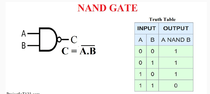
NAND GATE
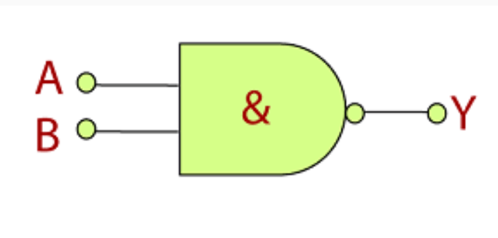
In digital electronics, a NAND gate (NOT-AND) is a logic gate which produces an output which is false only if all its inputs are true; thus its output is complement to that of an AND gate. A LOW (0) output results only if all the inputs to the gate are HIGH (1); if any input is LOW (0), a HIGH (1) output results. A NAND gate is made using transistors and junction diodes. By De Morgan’s laws, a two-input NAND gate’s logic may be expressed as A • B=A+B, making a NAND gate equivalent to inverters followed by an OR gate.
The NAND gate is significant because any boolean function can be implemented by using a combination of NAND gates. This property is called functional completeness. It shares this property with the NOR gate. Digital systems employing certain logic circuits take advantage of NAND’s functional completeness.
The function NAND(a1, a2, …, an) is logically equivalent to NOT(a1 AND a2 AND … AND an).
One way of expressing A NAND B is {\displaystyle {\overline {A\land B}}}{\displaystyle {\overline {A\land B}}}, where the symbol {\displaystyle {\land }}{\displaystyle {\land }} signifies AND and the bar signifies the negation of the expression under it: in essence, simply {\displaystyle {\displaystyle \neg (A\land B)}}{\displaystyle {\displaystyle \neg (A\land B)}}.
NAND gates with two or more inputs are available as integrated circuits in transistor-transistor logic, CMOS, and other logic families.
Truth table
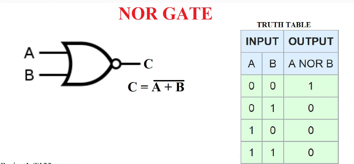
NOR GATE
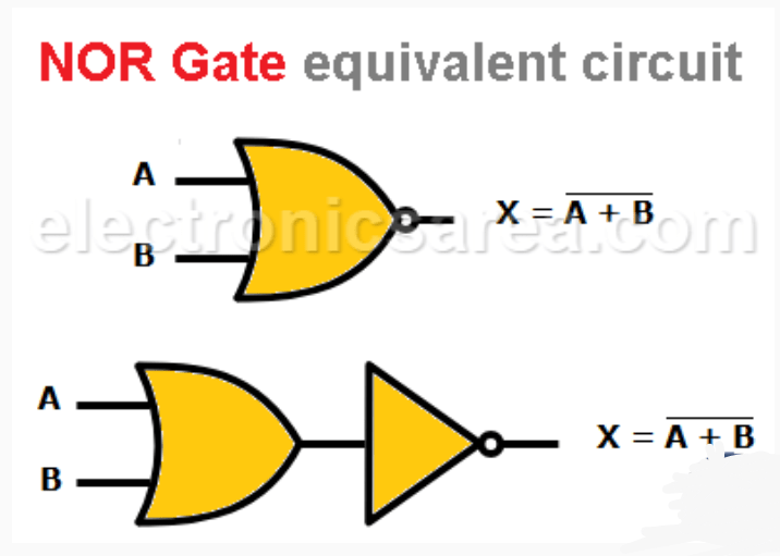
The NOR gate is a digital logic gate that implements logical NOR – it behaves according to the truth table to the right. A HIGH output (1) results if both the inputs to the gate are LOW (0); if one or both input is HIGH (1), a LOW output (0) results. NOR is the result of the negation of the OR operator. It can also in some senses be seen as the inverse of an AND gate. NOR is a functionally complete operation—NOR gates can be combined to generate any other logical function. It shares this property with the NAND gate. By contrast, the OR operator is monotonic as it can only change LOW to HIGH but not vice versa.
Truth table
XOR GATE
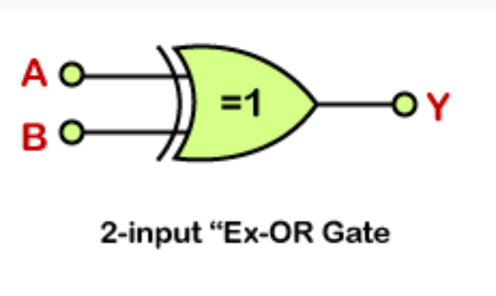
XOR gate (sometimes EOR, or EXOR and pronounced as Exclusive OR) is a digital logic gate that gives a true (1 or HIGH) output when the number of true inputs is odd. An XOR gate implements an exclusive or ({\displaystyle \nleftrightarrow }\nleftrightarrow) from mathematical logic; that is, a true output results if one, and only one, of the inputs to the gate is true. If both inputs are false (0/LOW) or both are true, a false output results. XOR represents the inequality function, i.e., the output is true if the inputs are not alike otherwise the output is false. A way to remember XOR is “must have one or the other but not both”.
XOR can also be viewed as addition modulo 2. As a result, XOR gates are used to implement binary addition in computers. A half adder consists of an XOR gate and an AND gate. Other uses include subtractors, comparators, and controlled inverters.
The algebraic expressions {\displaystyle A\cdot {\overline {B}}+{\overline {A}}\cdot B}A \cdot \overline{B} + \overline{A} \cdot B or {\displaystyle (A+B)\cdot ({\overline {A}}+{\overline {B}})}{\displaystyle (A+B)\cdot ({\overline {A}}+{\overline {B}})} or {\displaystyle A\oplus B}A\oplus B all represent the XOR gate with inputs A and B. The behavior of XOR is summarized in the truth table shown on the right.
Truth table

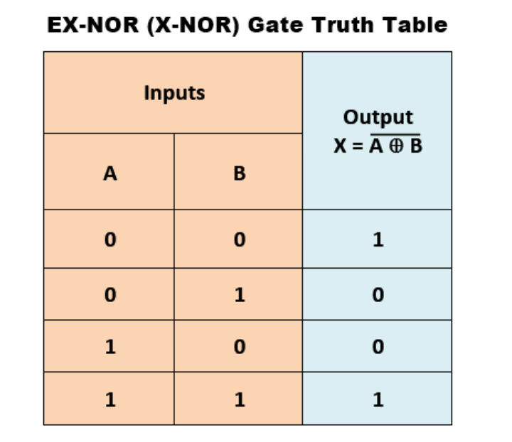
XNOR GATE
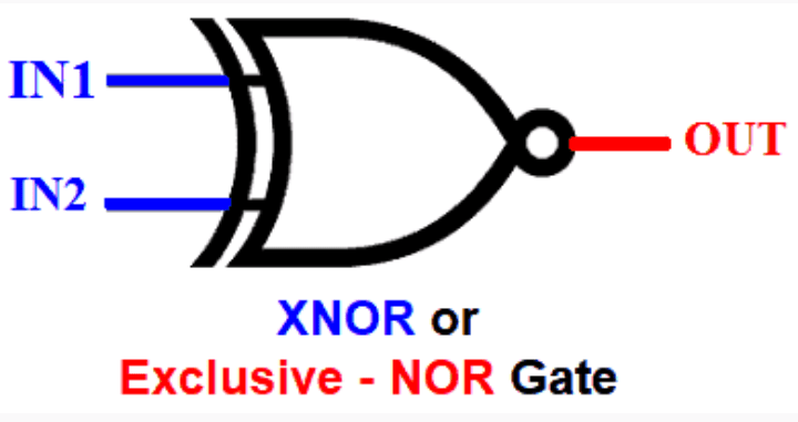
The XNOR gate is a digital logic gate whose function is the logical complement of the Exclusive OR gate. It is equivalent to the logical connective from mathematical logic, also known as the material biconditional.
Truth table